

Page 1
Introduction to SAW Filter Theory & Design Techniques
Introduction
API Technologies offers a wide range of high quality standard and
custom Surface Acoustic Wave (SAW) product solutions. API believes
in a flexible approach and possesses high volume capability and world
wide support.
In theory, an ideal filter would possess no loss, an instantaneous
transition from the pass band to the stop band, infinite stop band
attenuation, no signal distortion introduced by the filter and have
very small size and cost. In reality, many tradeoffs need to be
considered when selecting a filter for a system design. An advantage
of SAW filter technology is the realization of parts with reduced size
and weight; hence, a lower cost than other filter technologies since
the same type of process equipment that IC manufacturers rely upon
can be adapted for use to manufacture a SAW product.
This white paper will present some general SAW theory and
performance as well as applications to help guide the RF designer.
SAW Fundamentals
1. Overview
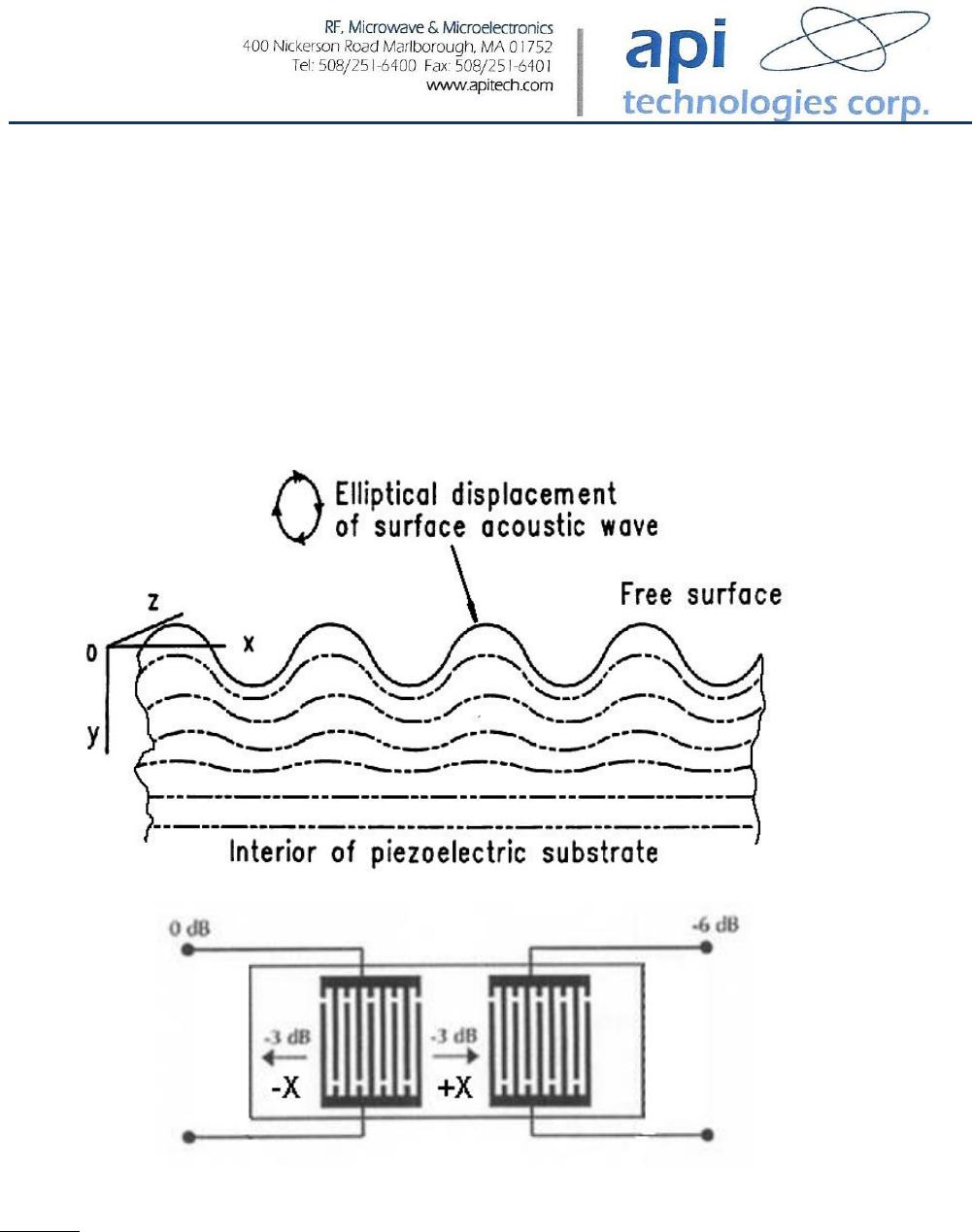
A SAW filter operates by converting electrical energy into acoustic or
mechanical energy on a piezoelectric material. This piezoelectric
effect is initiated by introducing two interdigital transducers. The
input transducer creates acoustic waves from the incident electrical
signal and the output transducer receives the acoustic waves (Figure
Page 2
1a), converting them back into electrical energy. These waves are
generated equally in both the +X and -X direction by the transducer
and this is known as a bidirectional transversal filter. Since the
desired wave to be converted is only ½ of the total (+X direction) a
loss of 3 dB is observed; for the input and output transducer
together, the resulting processed signal will possess an insertion loss
of 6 dB (Figure 1b).
(a)
(b)
Figure 1: (a) Diagram of a Surface Acoustic Wave travelling on substrate surface. (Courtesy of
C.K. Campbell, Ph.D.: Supplemental notes on lectures on SAW Devices, 1985), (b) Bi-directional
operation of a typical transversal device with equal SAW generation in -X and +X directions.
(Courtesy of ‘SAW Fundamentals’, SAWTek, 2/15/2001, p. 2)
Page 3
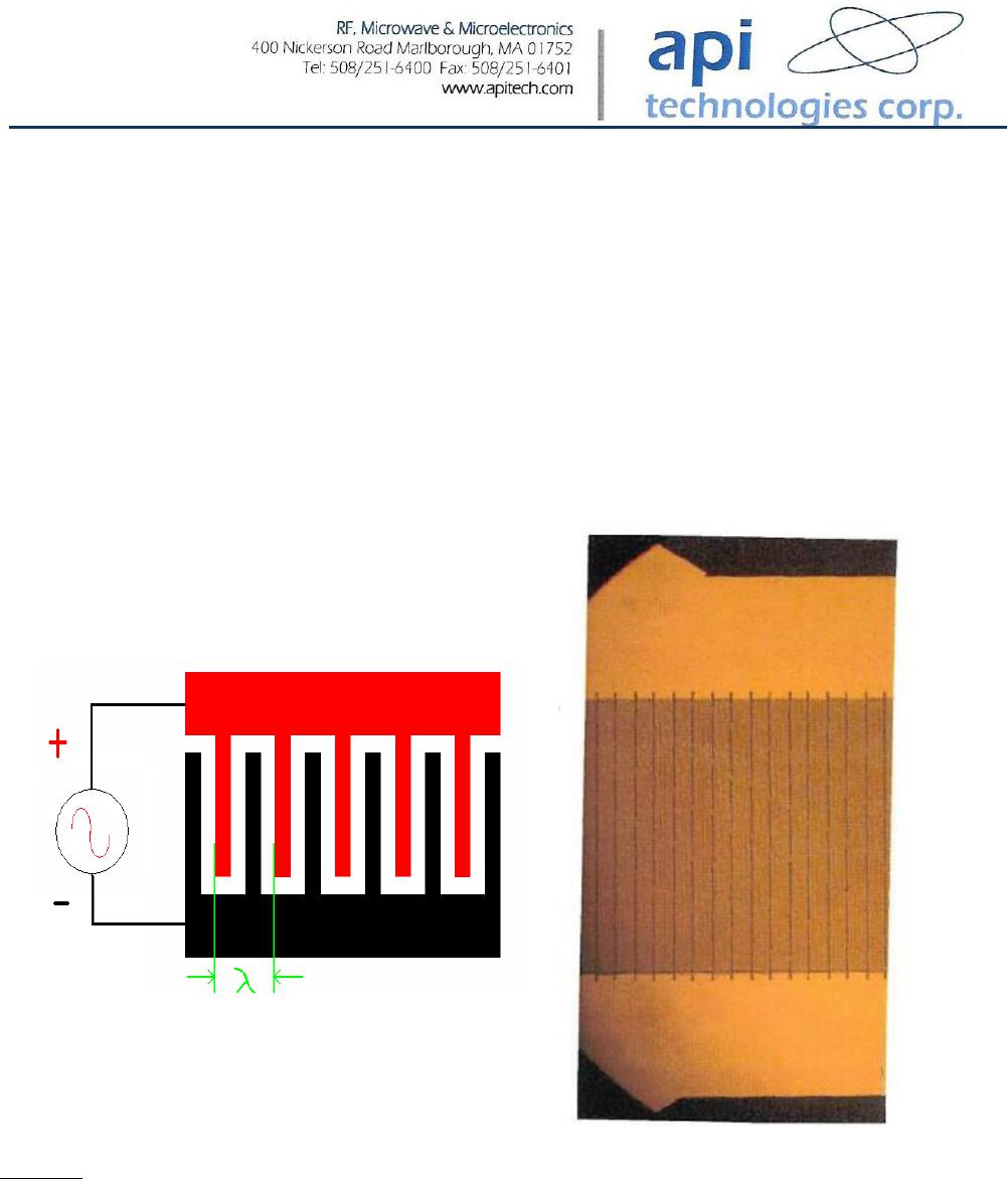
Each transducer is composed of periodic interdigital electrodes
connected to two bus bars as shown in Figure 2. The bus bars are
connected to the electrical source or load. A single interdigital
electrode will act as an acoustic source or detector, and the amplitude
will be determined by the electrode length, and the phase will be
given by the electrode’s position. The wavelength (λ) of the
electrodes and neighboring spaces determines the operating
frequency for the SAW device.
Figure 2: Diagram of a basic transducer and a photograph. Golden colored area represents the
patterned metal against the piezoelectric substrate (Courtesy of M. Schweyer, API Technologies)
With this general arrangement, the acoustic energy, concentrated at
the crystal’s surface, is easily accessible for signal processing.

Page 4
2. Piezoelectric Materials Used for SAW Product
Table 1 show the most common materials used for the manufacture
of SAW product. Each material possesses qualities that work best for
a certain segment of each SAW filter type.
Substrate
Velocity
(m/s)
Tc (ppm/ºC)
Coupling
Coefficient (K
2
)
Application
YZ Lithium
Niobate
3488
94
0.045
Wide band filters, Long
delay time delay lines
128º Lithium
Niobate
3992
74
0.055
Wide band filters
Quartz
3158
-0.033 ppm/ºC
2
0.00116
Narrow band filters, Short
delay lines, Resonators
112º Lithium
Tantalate
3290
18
0.0075
Mid band filters
41º Lithium
Niobate
4792
50
0.172
Low loss filters
64º Lithium
Niobate
4792
70
0.113
Low loss filters
42º Lithium
Tantalate
4022
40
0.076
Low loss filters
Table 1: A tabulation of substrate materials typically used in SAW applications is shown.
The Tc value, temperature coefficient, represents the shift in center
frequency versus the operating temperature of the SAW component.
Except for the Quartz substrate, the filter will shift upwards at lower
temperatures and downwards at higher temperatures in a linear
fashion. These shifts are accounted for in the design of the SAW by
adding a temperature shift component to the pass band requirement
and subtracting it from the stop band requirement.

Page 5
For quartz, the temperature shift is downwards parabolic with a
turnover temperature value where the temperature coefficient is zero.
The turnover temperature can be set by using quartz with different
cut angles for best overall performance over the customer’s
temperature range.
The coupling coefficient (K
2
) represents how efficient the material is
at producing an acoustic wave. Materials with larger K
2
values
produce stronger acoustic waves and generally possess less loss per
unit of delay (substrate length). This allows for a wider filter or
longer delay line.
3. Transversal SAW Devices
Transversal SAW devices are generally designed using a Finite
Impulse Response (FIR) technique with the Fourier transform. The
transducer is conceived in the time response. When transformed to
the frequency response, the general filter shape is produced. Figure 3
shows a few examples of this process.